github.com/lestrrat-3d

A Go toolchain for CAD,
from typed units up to rendered pixels.

Five libraries that stack into a headless CAD pipeline, plus the tools built on top of it. Everything here is driven from code — no GUI, no document format, no hidden ambient units.

All repositories The stack

The stack

Each layer depends only on the ones beneath it, and never the other way around. Any layer is usable on its own.

  1. solidlens Renders a mesh to pixels
  2. decad 3D bodies, features, verification
  3. sketch Parametric 2D constraint solving
  4. r3 Vectors, frames, rigid transforms
  5. units Typed quantities and their kinds

Libraries

units

Units of measure for Go.

A Value is a magnitude paired with the unit it is expressed in. A Kind is a vector of exponents over length, mass and angle, so kinds compose: multiply two lengths and you get an area, divide mass by volume and you get a density. Asking for a length in degrees returns an error rather than a silent reinterpretation, which is how the classic CAD-API trap — 2 quietly meaning 2 radians — stops happening.

w := units.Millimeters(100)
in, err := w.In(units.Inch)       // 3.937...
_, err = w.Convert(units.Degree)  // error: a length is not an angle

Gostandard library only

r3

Coordinate math for Euclidean 3-space.

A Vec vector type, an orthonormal right-handed Frame that carries the transform between a plane's local (u, v, w) coordinates and world (x, y, z), and a Transform for rigid motion of the space itself. Angles are typed, so no bare radians cross an API boundary. Points translate and directions do not.

spin, err := r3.RotationAround(
    r3.NewVec(10, 0, 0), r3.NewVec(0, 0, 1), units.Degrees(30),
)
p := spin.Apply(pt)      // a POINT: rotated, then moved
n := spin.ApplyDir(nrm)  // a DIRECTION: rotated only

Godepends on units

The word 'sketch' in outlined letters over a CAD grid and frame, above the tagline 'A headless parametric 2D sketch engine'

sketch

A headless parametric 2D sketch engine, in the spirit of Fusion's sketch environment.

You build points, lines, circles, arcs, ellipses and splines in code, tie them together with geometric and dimensional constraints, and a Levenberg–Marquardt solver moves the geometry until every constraint holds at once. Dimensions are ordinary editable values, so changing one and re-solving updates the sketch.

  • A Fusion-like constraint set: coincidence, tangency, parallel, perpendicular, symmetry, equality and more.
  • Degrees-of-freedom and redundancy analysis, conflict detection, and a multi-solution ambiguity probe.
  • Trim, extend, break, fillet, chamfer, mirror, pattern and offset on committed geometry.
  • Closed-region profile detection with exact areas and hole nesting.
  • Export to SVG and PNG — optionally annotated with dimensions and constraint glyphs — plus DXF R12 and lossless JSON.
w := sketch.NewWorld()
s, err := w.CreateSketch(w.XY())

a, b, d := s.CreatePoint(0, 0), s.CreatePoint(18, 2), s.CreatePoint(1, 13)
ab, ad := s.CreateLine(a, b), s.CreateLine(a, d)
s.Fix(a)                                    // ground one corner
s.AddConstraint(sketch.NewHorizontal(ab), sketch.NewVertical(ad))

width := sketch.NewDistance(a, b, 20)       // a driving dimension
s.AddConstraint(width)

res, err := s.Solve(ctx)                    // res.DOF == 0: fully constrained
width.Set(35)                               // re-solve and the geometry follows

Godepends on r3, units
Dimensional DECAD lettering rendered from decad solids against a pale blue-gray background

decad work in progress

Deconstructed CAD: a headless CAD engine for Go.

The 3D modeling layer above sketch and r3. It exists so that a part can be proven before anyone commits to building it in real CAD software: is the body watertight, does it self-intersect, what is its volume and centroid, do these two bodies collide, is any wall thinner than the end mill that has to cut it. Being wrong here is cheap.

The public API is landing incrementally against an approved design, so what the package exports today is the leading edge of a larger contract.

doc := decad.New()
body, err := doc.Extrude(s, s.Profiles()[0],
    decad.Distance{D: units.Millimeters(10), Dir: decad.Along})

vol, err := body.Volume()
fmt.Println(vol.Value, vol.Exactness)       // 60000 mm^3 Exact

report, err := doc.Verify(ctx)              // solidity, quantities, interference
fmt.Println(report.Status, report.Trustworthy())
// Sound true

Godepends on sketch, r3, units

The word Solidlens rendered in 3D above a cyan sphere, a violet pyramid, and a coral cube, on a deep navy background

solidlens

A pure-Go headless raster renderer for triangle meshes.

It loads STL, 3MF and OBJ files, or takes a *decad.Mesh directly, and renders a configured scene to an image.RGBA or a PNG stream. The scene owns the camera, materials, directional and point lights and background; the renderer owns only the output size, so independent scenes render concurrently.

Edge drawing follows the geometry rather than the tessellation: a line appears on a border, on a silhouette, or where two faces meet above the crease angle, so a curved surface keeps its outline instead of turning into a grid of facets.

Goreads STL, 3MF, OBJ

Built on the stack

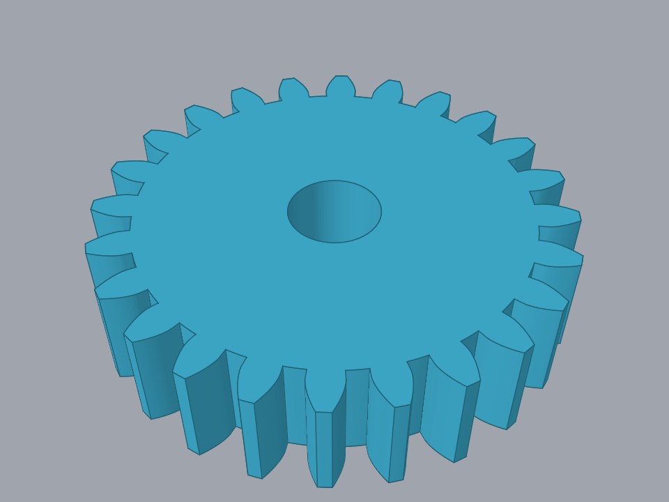
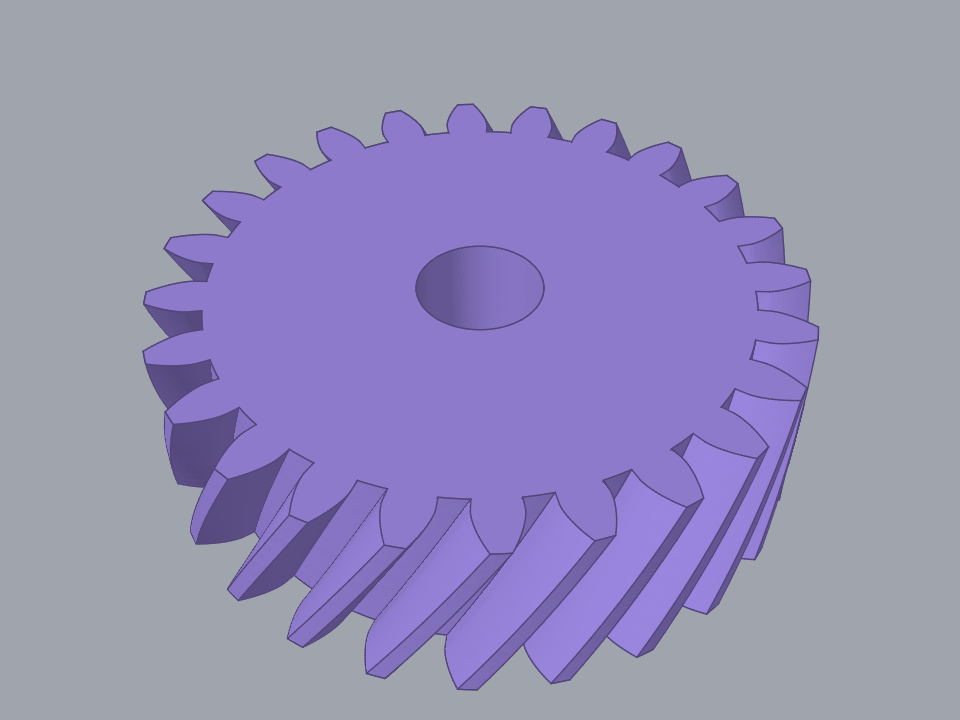
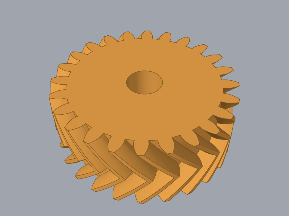
A cyan spur gear with a central bore, teeth running straight across the rim A violet helical gear, its teeth twisting evenly around the rim An amber herringbone gear, its teeth meeting in a chevron at mid-height

fusion360-gear-generator work in progress

Yet another gear generator for Fusion 360 — this one leaves fully constrained sketches behind.

Spur, helical, herringbone and bevel gears, plus a cycloidal drive that builds its lobed discs, eccentric cam, ring housing and output plate as separate sub-components. Gears can be placed on any plane, surface or point pair, and the sketches come out fully constrained, so moving or editing a generated gear behaves.

Those images are gears the generator actually cut, rendered with solidlens.

PythonFusion 360 add-in